Welding Fume Local Exhaust System
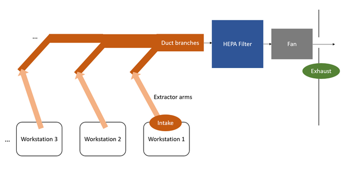
Inhaling welding fumes is hazardous and can lead to health issues for welders. Consequently, I am committed to designing a fume exhaust system for this project. The system will incorporate a centrifugal fan, a filter compartment, a duct system, and individual local extractor arm branches for each workstation.

Air Flow Chart

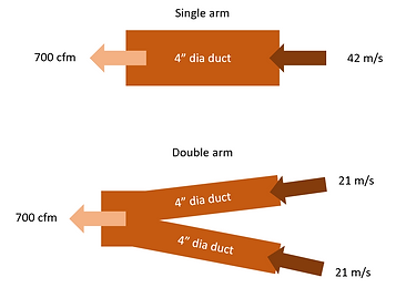
After conducting research on fume extractors, HVAC systems, ducting, and filters, it has been determined that to achieve effective ventilation for welding fume, an intake air velocity of 10-13 m/s is required. Considering a 4" diameter arm, the fan should provide an airflow ranging from 166 to 216 cfm, while increasing the duct size will request larger airflow.
I decided to build a portable prototype extractor with a spare 700 cfm fan we have in-house, to test how much pressure loss there will be in the ducting system. By connecting a single arm and double arm to the fan, the ideal intake velocity is 42 m/s and 221 m/s respectively.
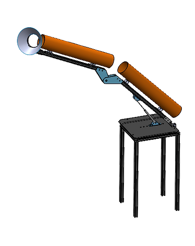
Shown on the right is the initial extractor arm design for the 1st prototype. To save the budget, the assembly contents only the essential parts for testing, including 30GA duct pipes and fittings, T-slotted frame, a gas spring, and a few sheet metal brackets that we'll produce at our machine shop.
This prototype will allow us to test whether thee duct size is large enough to capture the fume, the air velocity at various distance, and 3-dimensional rotation feature.
Next Steps:
-
Measure intake air speed and estimate pressure loss/arm with prototype.
-
Calculate new fan airflow needed for multiple branches and select the appropriate fan.
-
Design new ducting system with detail.
-
Install, test, and implement new system.

flex duct at the joints